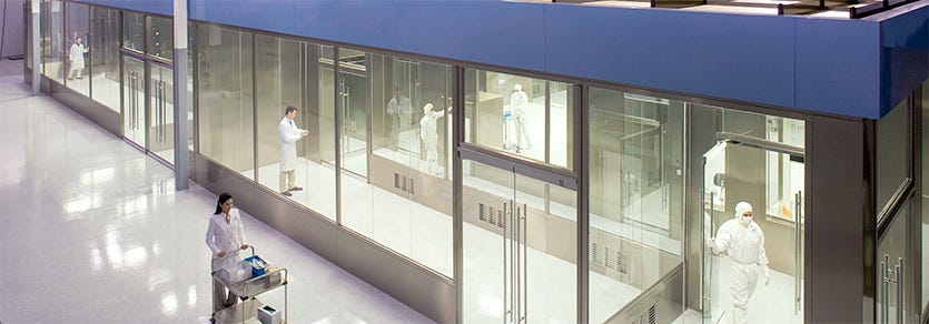
Terra Universal will certify its cleanrooms to guarantee “as built” compliance with cleanliness standards. What matters, though, is how the cleanroom performs in real world applications—in your application, with your personnel and processing equipment.
Careful consideration of these operating conditions will help you select the configuration that meets your requirements and fits your budget!
Cost vs. Coverage: Evaluating FFU Placement
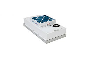
The cleanest modular cleanroom incorporates filter/fan units (FFUs) in every 2' x 4' (610 mm x 1219 mm) ceiling bay. This near-100% ceiling coverage provides a laminar flow of filtered air to quickly remove contaminants from the cleanroom, meeting ISO 3 or ISO 4 (Federal Standard 209(E) Class 1 or Class 10) environments (depending on the filter types selected, HEPA or ULPA).
Of course, 100% ceiling coverage requires substantial investment in FFUs, especially if the cleanroom is very large. In most applications, adequate cleanliness can be achieved with substantially less filter coverage. How many modules you need depends on several operational variables.
Cleanliness Rating
Most cleanroom facility engineers agree that ISO 3 and ISO 4 applications require near-100% ceiling coverage, producing a laminar flow of clean air traveling downward at a velocity of about 90 feet/minute, 0.5 m/s, (measured 12", 305 mm, below the filter face). This design ensures a positive pressure inside the cleanroom, which blocks the influx of contaminants through leaks in the cleanroom wall or curtain, and guarantees swift removal of particles generated by people or process equipment inside the enclosure.
Ventilation Efficiency
For less critical contamination requirements, experts correlate ventilation efficiency (i.e., the ability to remove contaminants and meet a cleanliness standard) with both the velocity of filtered air passing through the room and also the number of air changes completed in a given time. The air-change figures are usually expressed as a range (see Table 1).
The breadth of these ranges reflects how dramatically people and processes affect cleanliness. Low-end figures within each contamination class generally indicate air velocity and air change requirements for an "as built" or "at rest" facility—one in which no people are present and no contaminating processes are under way. In the presence of higher degrees of contamination (resulting from many cleanroom workers or contaminating manufacturing processes), more air changes are required to maintain the desired cleanliness standard. In fact, many manufacturers insist on as many as 720 air changes per hour to meet ISO 4 or cleaner requirements.
Deciding on the appropriate velocity and air changes for your application generally requires careful evaluation of such factors as number of personnel, effectiveness of garbing protocol, frequency of access, and cleanliness of process equipment. Once you have established the required air change figure, you can calculate the number of FFUs required by using this formula:
No. of FFUs = (Air Changes/Hour ÷60) x (Cubic ft. in room÷ 650*)
*CFM output of a loaded FFU at medium speed.
Thus, to meet ISO 5 standard using the low-end air change recommendation (240/hour) inside a 12' x 12' x 7' (3658 mm x 3658 mm x 2134 mm) cleanroom, with 1008 cu. ft. (28.5 m³) of volume, requires 7 FFUs. To meet the same standard using the high-end air change recommendation (480/hour) requires 13 FFUs. For your calculations, round up fractions to avoid under-performance.
Applying this formula to the remaining cleanliness classifications gives us guidelines for ceiling filter coverage (see Table 2).
| Table 1: Recommended Air Velocity Rates | |||
| Class Iso 146144-1 (Standard 209E) |
Average Airflow Velocity m/s (ft/min) |
Air Changes Per Hour |
|
| ISO 8 (Class 100,000) | 0.005 - 0.041 (1 - 8) | 5 - 48 | |
| ISO 7 (Class 10,000) | 0.051 - 0.076 (10 - 15) | 60 - 90 | |
| ISO 6 (Class 1,000) | 0.127 - 0.203 (25 - 40) | 150 - 240 | |
| ISO 5 (Class 100) | 0.203 - 0.406 (40 - 80) | 240 - 480 | |
| ISO 4 (Class 10) | 0.254 - 0.457 (50 - 90) | 300 - 540 | |
| ISO 3 (Class 1) | 0.305 - 0.457 (60 - 90) | 360 - 540 | |
| ISO 1-2 | 0.305 - 0.508 (60 - 100) | 360 - 600 | |
| Note: Actual average velocity and air changes required may vary depending on the application and floor plan. Source: Institute of Environmental Science | |||
| Table 2: Recommended Ceiling Filter Coverage | ||
| Class | Ceiling Coverage | |
| ISO 8 (Class 100,000) | 5 - 15% | |
| ISO 7 (Class 10,000) | 15 - 20% | |
| ISO 6 (Class 1,000) | 25 - 40% | |
| ISO 5 (Class 100) | 35 - 70% | |
| ISO 4 (Class 10) | 50 - 90%* | |
| ISO 3 (Class 1) | 60 - 100%* | |
| ISO 1-2 | 80 - 100% | |
| Note: Actual average velocity and air changes required may vary depending on the application and floor plan, including ceiling height. * ULPA filters required in ISO 3 and 4 applications. HEPA filters required for all others. |
||
Partitions: Creating "Clean Zones" to Optimize Performance and Economy
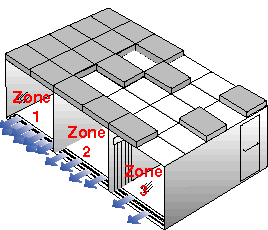
Of course, not every square inch of cleanroom space is used the same way. Often, performance can be optimized—and costs reduced—through the use of partitions to create multiple clean zones with varying degrees of cleanliness.
As requirements change, partitions can be removed and filter modules added or rearranged as needed. Highest ceiling filter density can be reserved for areas with the cleanest requirements and the most particles generated. Areas with fewer people or less demanding particle requirements are configured more economically with fewer filters.
Typical Configurations Using Partitions
Zone 1: Most Particle Sensitive. ISO 3 (ULPA) 100% Filter Coverage
Zone 2: Packaging Area. ISO 5 50% Filter coverage
Zone 3: Staging Area ISO 6 30% Coverage
Note: These are typical, not guaranteed, contamination levels for each of the filter configurations depicted. Actual values are related to such variables as the number of garbed personnel present, their activity level, the cleanliness of outside air, and contaminants emanating from process equipment.
Your Best Approach?
Thorough Evaluation and Careful Monitoring: Because no simple formula is right for every application, Terra contamination specialists work with you to design an effective, economical cleanroom configuration and monitoring program. If requirements change, our modular design allows you to add filters, lighting, ionization, or additional floor space—all at a fraction of the cost you'd face with other systems.
Cleanroom Lighting
Terra offers three lighting modules.
For applications that do not require 100% FFU ceiling coverage, 2' x 4' (610 mm x 1219 mm) illuminators can be positioned in unused ceiling grids.
For applications that require total or near-total FFU ceiling coverage, teardrop and flow-through lighting modules are available. Teardrop fluorescent lights mount to the ceiling grid below the FFU. Their aerodynamic design does not interfere with the laminar airflow. Each of these single-tube lights requires 6" (152 mm) of vertical clearance below the FFU filter face.
As an alternative to teardrop lights, you can select 2' x 4' (610 mm x 1219 mm) flow-through lights, which are stacked below the FFU. Flow-through lights add 4 3/4" (121 mm) to the ceiling height but require no vertical clearance below the filter face, making them ideal for low-ceiling cleanrooms.


